
Find out how to Measure Inside Resistance of a Battery
[ad_1]
Introduction
A generally encountered school-level Physics sensible is the willpower of the inner resistance of a battery – usually an AA or D cell. Usually that is based mostly round a easy mannequin of such a cell as a supply emf in collection with a small resistor. The cell is linked to a resistive load and (within the easiest case the place load resistance is thought) solely open circuit voltage and cargo volts must be measured.
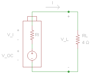
Then: $$r_i=frac{V_I}{I} =frac{Delta V}{I} $$ the place $$Delta V = V_{OC}-V_{L}$$ and $$I=frac{V_L}{R_L} $$.
It needs to be famous that the above illustration of a battery as a easy fixed voltage supply in collection with a small resistor is a handy simplification of fairly complicated battery chemistry. In apply, one finds that neither the open circuit voltage (emf) nor the inner resistance stays fixed as is assumed on this mannequin. Each fluctuate relying upon the “state of cost” (SOC) or “depth of discharge” (DOD) of the battery. So experiments to find out inner resistance needs to be confined to hundreds for which there’s minimal or negligible discharge throughout measurement. There are extra complicated electrical fashions of battery chemistry and these will higher approximate the battery’s time-dependent electrical output throughout discharge.
On this article, we start by describing difficulties skilled making an attempt the direct measurement described above. We then talk about the “traditional” college experiment for the willpower of inner resistance and develop some approximation formulation. These could also be used to find out circuit parameters from regression evaluation of present vs conductance or load voltage vs conductance in addition to the “conventional” load voltage vs amps.
Lastly, we revert to the unique easy technique of direct measurement albeit by exploiting the “battery take a look at” setting discovered on (some) multimeters. This setting does not more than present a resistive load for the battery underneath take a look at and the “battery take a look at” voltage studying is subsequently a load voltage. As meter leads carry present from the battery terminals by means of the load, we have now to bear in mind lead resistance when utilizing this technique.
Experimental Temporary
Within the explicit “experimental temporary” given to some college students attending classes right here, inner resistance was to be decided utilizing a “do-it-yourself” resistor of roughly ##;4 Omega## for the load. Measurements of open circuit voltage, terminal (load) voltage, and present had been to be made with a single multimeter. One quickly found that an ##approx 4 Omega## resistor linked to a typical AA cell would draw a substantive present and that measurement of terminal voltage was problematic on account of that voltage dropping even because the measurement was taken. Present measurements suffered equally. Alternatively, if load resistance had been elevated to attempt to ‘stabilize’ the readings, one would discover there was scarcely any terminal voltage drop. So the requirement is to attempt to discover a resistance or resistance vary whereby the present drawn over the time span of measurement wouldn’t considerably have an effect on open circuit (and therefore terminal) voltage while on the identical time offering a measurable terminal voltage drop.
Revised Experimental Temporary
The traditional college experiment to find out the inner resistance of a cell doesn’t require the measurement of open circuit voltage since this parameter is as a substitute decided from linear regression. It’s the y-intercept of a straight line having a gradient equal to the cell’s inner resistance in line with the equation: $$V_L = textbf{ℇ} – Ir_i$$ Right here ##I## and ##V_L## are the x and y variables respectively with ##textbf{ℇ}## – the cell emf – and ##r_i## – inner resistance – being obtained as regression coefficients of the y-intercept and gradient respectively. In accordance with the unique experimental temporary (use a “do-it-yourself” resistor), the present was various by utilizing an uncovered pencil lead as a variable resistor. A second pencil lead was used as a present limiting resistor (##R ge 8.8 Omega##). It was not anticipated that college students would have multiple multimeter at their disposal.
Strictly talking, it is just essential to take present and voltage readings however right here we embrace resistance readings as nicely. We have to talk about why there’s a discrepancy between the measured resistance values (first column of the desk under) and Ohm’s regulation calculated values (final column of the desk under). One other salient level about this dataset is that the open circuit voltage has remained roughly fixed all through the set of readings. This is essential since a continuing cell emf is assumed within the equation ##V_L = textbf{ℇ} – Ir_i.##
Opposite to the unique experiment temporary (indicating the usage of just one meter), it’s essential to make use of two meters – one for the amps and one for the volts. The reason being that readings of voltage and present must be taken concurrently to make sure that the pairs match up appropriately. If (for instance) a multimeter was used first to measure volts after which (individually) amps, the readings would NOT match up as a result of when the multimeter measures present, it routinely introduces non-negligible resistance into the circuit. This experimental element was noticed by the creator. Nonetheless, the rationale was not appreciated till being suggested about it in a PF dialogue thread on the identical subject (battery inner resistance).
Desk of Measurements and Calculated Values
| Resistance | Present | Open circuit volts | Load Volts | R calculated |
| (Ohms) | (milli-amps) | (milli-volts) | (milli-volts) | (Ohms) |
| 8.8 | 138.4 | 1521 | 1486 | 10.74 |
| 18.6 | 73.8 | 1523 | 1501 | 20.34 |
| 23.9 | 58.6 | 1521 | 1505 | 25.68 |
| 13.6 | 97.6 | 1522 | 1495 | 15.32 |
| 21.7 | 63.8 | 1521 | 1503 | 23.56 |
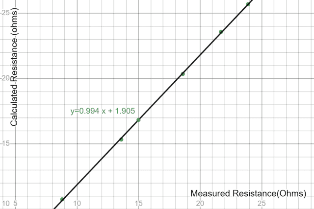
Regression Evaluation: Measured vs Ohm’s Regulation calculated Resistance
A plot of calculated resistance vs measured resistance yields (as anticipated) a gradient ##approx 1## however there’s a particular “offset” or y-intercept worth (##approx 1.9 Omega##) which this creator (anyway!) couldn’t discover any clarification for.
https://www.desmos.com/calculator/mw5bq32df9
A question was placed on PF and the next clarification was obtained from PF consumer @TomG:
You talked about that you simply used the identical meter to measure the present. The Present vary of a digital ammeter has some low, non-zero, inner resistance, which might add to your efficient load resistance. Has this been taken into consideration?
https://www.physicsforums.com/threads/battery-internal-resistance.1016677/post-6650450
So the offset indicated within the regression evaluation above arises from the truth that when the present was measured, a further resistance (that of the ammeter) was launched into the circuit. Once we plot load voltage vs present, this doesn’t matter because the measured present is for the whole circuit resistance and corresponds to an identical load voltage measurement. Nonetheless, we must always definitely be asking questions as to why Ohm’s regulation calculation of resistance yields values which can be practically 2 ohms completely different from the measured values.
Even with an ##8.8;Omega## present limiting resistor, there have been nonetheless issues with fluctuating voltage measurements when utilizing a single AA cell. Because of this, the above dataset was measured with 2 related AA cells in parallel on the understanding that the inner resistance obtained could be half that for a single AA cell. Nonetheless, this setup is just not excellent since it’s certainly not assured that even related AA cells may have the identical inner resistance. The parallel connection additionally introduces issues with ‘fitment resistance’ – a subject to be additional mentioned on this article. Be that as it could, it’s nonetheless instructive to look at graphs and regression evaluation of the information obtained.
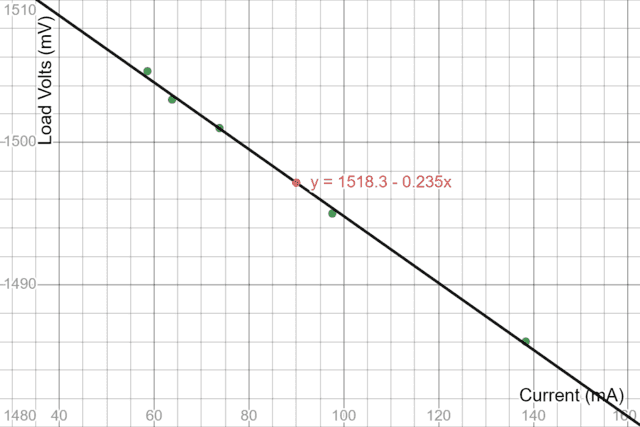
Regression Evaluation: Load Voltage vs Present
https://www.desmos.com/calculator/3cqsrmwbvv
The plot above is typical of what one may anticipate from the “traditional college experiment” described within the video hyperlink above. For the parallel pair the regression fitted ‘trendline’ exhibits an inner resistance of ##approx 0.235 ;Omega## and a (parallel) cell emf of ##approx 1518.3; mV##. The latter could be very near the measured open circuit voltage(s) within the dataset above. The discrepancy (about 3 milli-volts) is most certainly attributable to “fitment resistance”. When making an attempt to find out a resistance worth as little as that obtained above, one must be very conscious of varied small resistance values that might have an effect on the worth obtained. For instance, one set of take a look at leads that I used has a resistance of about ##0.113 Omega## and one has to rigorously take into account when and when not lead resistance will impression upon the willpower of an AA cell’s inner resistance.
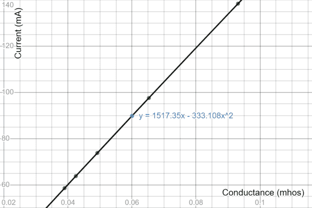
Regression Evaluation: Present vs Conductance
Contemplate the equation: $$ I = frac {textbf{ℇ}}{R+r_i}=frac {textbf{ℇ}}{Rleft(1+frac{r_i}{R}proper)}approx frac{textbf{ℇ}}{R}left(1-frac{r_i}{R}proper).$$ The approximation is obtained from a one-term binomial enlargement of ##left(1+frac{r_i}{R}proper)^{-1}## and shall be more and more correct the smaller ##r_i## is towards R – ie for ##r_i<<R##. By way of conductance G (reciprocal of resistance), we might re-write the approximation as $$Iapproxtextbf{ℇ}G-textbf{ℇ}r_i G^2$$ and a quadratic regression evaluation of the plot I vs G ought to yield the identical parameters (##r_i## and ##textbf{ℇ}##) because the linear mannequin. To acquire conductance readings, we use the prevailing dataset values by calculating the quotient ##frac{I}{V_L}##. We beforehand indicated why there could be an issue with the extra direct technique of calculating conductance because the reciprocal of resistance. All the identical, this explicit regression evaluation is extra suited to figuring out inner resistance from direct measurements of present and conductance. Maybe by utilizing a non-intrusive Corridor impact present sensor.
https://www.desmos.com/calculator/qhojl7ly1k
The graph is strikingly linear and we must always anticipate that since from the equation the time period ##textbf{ℇ}G## (representing an excellent battery) is by far the main element with the quadratic “correction” time period being very small. Nonetheless on condition that the quadratic co-efficient is the product ##textbf{ℇ}r_i## and the co-efficient of the linear time period is simply ##textbf{ℇ}##, we will divide the primary by the second to yield a worth of ##0.22;Omega## for ##r_i## in good settlement with the sooner worth obtained by linear regression of load voltage vs present. Whether or not quadratic regression has any explicit statistical benefit as in comparison with linear regression is a query we should depart to the statistics ‘gurus’. By way of the Excel ‘trendline’ match above, we have now set a zero intercept since theoretically there is no such thing as a fixed time period within the equation. Nonetheless, a pressured zero intercept might not be excellent from a statistical perspective.
In precept, we must always have the ability to use only one meter for this technique since technically solely a present studying is required. Nonetheless, this could imply that we’re utilizing exactly identified values of resistance/conductance in addition to a equally exact worth of ammeter resistance. This isn’t that straightforward to appreciate in apply except one has an instrument reminiscent of a milli-ohm meter (a second meter anyway!). And ideally a non-intrusive Corridor impact present sensor!
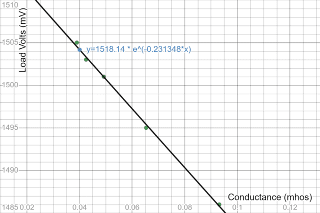
Regression Evaluation: Load Voltage vs Conductance
Contemplate once more the equation: $$ I = frac {textbf{ℇ}}{R+r_i}=frac {textbf{ℇ}}{Rleft(1+frac{r_i}{R}proper)}.$$ Given ##r_i<<R##, a mathematical ‘trick’ we will use to good impact right here is to jot down $$1+frac{r_i}{R} =1 + r_iG approx e^{r_iG}$$ in order that: $$ I approx {ℇ}{G}e^{-r_iG}implies V_L= {ℇ}e^{-r_iG}. $$ The benefit of this re-arrangement is that exponential regression on load volts vs conductance will instantly yield a worth for ##r_i##. And for plotting functions, one might calculate conductance immediately because the reciprocal of measured resistance albeit once more needing to know the resistance values as precisely as attainable.
In precept, we don’t want a present measurement and therefore needn’t be involved with the related complication of ammeter resistance. Nonetheless, on this explicit case, our desk of readings above was already obtained utilizing the “two-meter” technique so we’re once more figuring out conductance as ##frac{I}{V_load}##. Ideally, this explicit regression evaluation needs to be used to find out inner resistance from direct measurements of load voltage and conductance if we’re capable of precisely measure conductance or can supply high-accuracy resistors.
https://www.desmos.com/calculator/kngmrtkriz
The graph appears linear relatively than exponential for the easy purpose that over the actual area of conductance values, the exponential is certainly nicely approximated by a 1-term linear enlargement. Nonetheless the exponential regression match instantly yields ##r_i=0.231 Omega## and ##textbf{ℇ}=1518.14;mV##. The fixed ought to point out the open circuit voltage however right here there’s a discrepancy because the measured open circuit voltage is about 1521 millivolts. The most certainly reason for this discrepancy is “fitment resistance” whereby there’s a quick stretch of conductive materials from the battery terminal to the purpose at which the voltmeter (measuring load volts) is connected. When the battery attracts present to provide a load, this introduces a small voltage drop which might not be there if the voltmeter had been linked on to the battery’s constructive and damaging terminals.
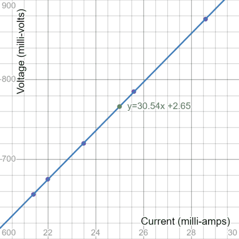
An Alternate Methodology utilizing Battery Check Mode
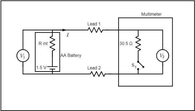
On one of many two meters used for this experiment, there’s a “battery take a look at” setting for both 1.5-volt or 9-volt batteries. It seems that this setting locations a load of 30.5 Ohms onto the battery (the 30.5-ohm worth was obtained from an Ohm’s regulation regression evaluation) and the voltage measurement (within the battery take a look at setting) is immediately throughout this resistance. That is very helpful since now one is instantly capable of calculate circuit present by dividing the measured voltage by 30.5. The open circuit voltage of the battery may also be measured and the voltage drop (underneath load) can therefore be calculated. Dividing this voltage drop by circuit present yields inner resistance. A observe on the load resistor worth of 30.5 ohms is that it was most likely rigorously chosen as being consultant of a “mid-range” AA battery load. The corresponding present draw is about 50 milliamps and an AA cell datasheet will present a “mid-range” discharge curve as measured at this present.
Sadly nonetheless, as identified by PF member @sophiecentaur, there’s a complication with this technique primarily as a result of it’s NOT a four-wire measurement (we might make it in order described within the Appendix under). Load present flows from the battery (underneath take a look at) by means of the meter leads en path to the load resistance (contained in the meter) so the worth of ‘inner resistance’ obtained would be the sum of lead resistance and battery inner resistance.
This complication could also be handled by taking measurements utilizing 2 separate units of leads (ideally similar pairs) and a 3rd measurement wherein each pairs of leads are linked in collection. The circuit diagrams under present these 3 measurements. Notice that open circuit voltage is nominally proven as 1.5 volts whereas the precise worth relies upon upon the AA cell one is testing/measuring. Notice additionally that within the diagrams, every pair of leads is represented by two resistors however ##R_2## and ##R_1## consult with the resistance of the respective lead pairs. ##R_{int}## is the inner resistance of the AA cell. The ##30.5;Omega## resistor is inner to the multimeter and connects when one change from studying DC voltage (open circuit) to DC load voltage underneath the “battery take a look at” setting.
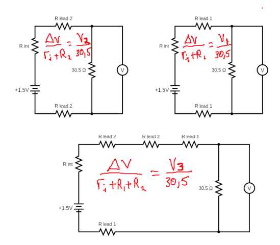
$$r_i = (r_i + R_1) + (r_i + R_2) – (r_i+R_1+R_2) $$ $$R_1 = (r_i+R_1) – r_i$$ $$R_2= (r_i+R_2) – r_i$$
Serendipitous by-products of this set of measurements are resistance values for the 2 units of lead getting used. It needs to be famous that since a 1 millivolt drop corresponds (roughly) to a resistance worth of twenty-two ohms, the latter is the decision restrict of this measuring system and the resistance values are all ##pm 11;mOmega##. As soon as lead resistance is thought, a single measurement will suffice for measuring the inner resistance of some other AA cell.
Desk of Outcomes: 4 Varta AA 2100 mAh batteries
| Battery | Voc mV | V1 mV | V2 mV | V3 mV | ri+R1 ohms | ri+R2 ohms | ri+R1+R2 | |
| 1 | 1368 | 1360 | 1363 | 1358 | 0.179 | 0.112 | 0.225 | |
| 2 | 1366 | 1358 | 1361 | 1356 | 0.180 | 0.112 | 0.225 | |
| 3 | 1365 | 1357 | 1360 | 1355 | 0.180 | 0.112 | 0.225 | |
| 4 | 1365 | 1357 | 1360 | 1355 | 0.180 | 0.112 | 0.225 | |
| ri ohms | R1 ohms | R2 ohms | Alternate | ri+R1 ohms | ri+R2 ohms | ri+R1+R2 | ||
| 0.067 | 0.113 | 0.045 | Calculation | 0.179 | 0.112 | 0.224 | ||
| 0.067 | 0.113 | 0.045 | 0.179 | 0.112 | 0.224 | |||
| 0.067 | 0.113 | 0.045 | ri + R = | 0.179 | 0.112 | 0.224 | ||
| 0.067 | 0.113 | 0.045 | 30.5*ln(Voc/Vl) | 0.179 | 0.112 | 0.224 |
Low Resistance Measurement
Within the above setup, there’s in fact nothing to stop us from changing the second set of leads with any low resistance worth. So we have now yet one more serendipitous by-product of this measurement approach. Particularly that it may be used to measure any low resistance values to an accuracy of ##pm 11 mOmega##. That is an order of magnitude higher than the resistance scale on the meter itself which is just good to ##0.1 Omega##.
An instance of sensible use of this system arose when the creator tried to measure the resistance of a set of 12-volt battery leap leads. It was found that the resistance was far too excessive (about 800 milli-ohms) and subsequent investigation revealed very poor crimp connections to the terminating alligator clips. The leads had been taken to a TV restore store the place the connections had been soldered down correctly and the leap leads now measure in at simply 45 milliohms.
A number of completely different lengths of galvanized metal wire had been measured and the proportionality between resistance and size was verified. In fact, a milliohm meter will do that process equally nicely however take into account price issue vs a ‘run of the mill’ multimeter such because the one this creator has used for the above measurements! One brings inside straightforward sight, the vital resistance vary between 0 and 1 ohms whereby lies a treasure trove of attention-grabbing scientific and/or engineering info!
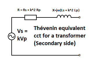
Thévenin Equal Circuit
Circuit illustration as a resistance (impedance within the case of a sinusoidal supply voltage) in collection with a continuing voltage supply is called a Thévenin equal circuit and finds in depth use in lots of scientific and/or engineering purposes wherein complicated bodily/electrical techniques are simplified accordingly. The battery circuit mentioned on this article is one such instance. One other very helpful instance is that of a transformer wherein, wanting into the 2 terminal secondary aspect, we see a simplified Thévenin equal consisting of an AC voltage supply (major voltage occasions turns ratio) in collection with an impedance R + jwL the place R is a sum of secondary winding resistance and ‘stepped up’ major winding resistance. The identical applies to the inductance L. The ‘step up’ co-efficient is the sq. of the turns ratio okay.
Related circuits are used to signify every section of 3-phase synchronous motors and 3-phase induction motors
Abstract and Conclusion
On this article, we have now explored numerous types of regression evaluation which can be used to find out the inner resistance of a battery (AA cell particularly). Given the three variables current in Ohm’s Regulation calculations, we will plot any two towards one another and acquire inner resistance by applicable regression evaluation. We have now talked about numerous sensible issues (and options) related to accumulating such information units.
We have now additionally described a completely completely different approach for figuring out inner resistance by exploiting the “Battery Check” setting which some digital multimeters make accessible. This system additionally permits the measurement of low resistance values on the whole. Low resistance measurement makes attainable a spread of various college science practicals in addition to discovering purposes in measuring the resistance of (for instance) battery jumper cables! Or for measurements of motor and transformer windings and for checking the standard {of electrical} connections.
The modeling circuit for a battery consists of a continuing voltage supply in collection with a resistor. This is called a Thévenin equal circuit and it’s typically attainable to interrupt down complicated circuitry into its Thévenin equal. When the supply voltage is sinusoidal, the Thévenin equal will present an AC supply with mounted frequency (usually 50Hz) in collection with an impedance represented by a fancy quantity.
Acknowledgments
This text stems from a protracted thread on battery inner resistance which the creator initiated after experiencing some technical difficulties with an related college sensible A number of PF mentors: contributed to this thread and I want to thank every of them for the numerous useful suggestions and sensible recommendation on how finest to conduct experiments/measurements of this nature. I’ve taken the freedom of together with hyperlinks to explicit posts from PF customers @DaveE and @Tom.G while the event of “An Alternate Methodology” was assisted in no small measure by feedback from @SophieCentaur.
The identical PF customers contributed additional solutions after I posted this text for evaluation. As well as, PF consumer @Anorlunda prompt the inclusion of a paragraph or two on the “Thévenin equal circuit” noting that {the electrical} mannequin of a battery is an instance of such. PF consumer @Rive prompt an early dialogue of this mannequin’s limitations and PF consumer @.Scott made the purpose that inner resistance is finest measured utilizing a consultant load. @Steve4Physics bolstered the purpose that measurements needs to be taken rapidly to keep away from modifications in battery emf in addition to battery heating which might have an effect on the resistance measurement.
Maybe too typically, we take this with no consideration however with out @Greg there could be no PF and no platform for insights such because the above.
Lastly, I want to sincerely thank Clinton and Douglas at Armcoil Afrika who had been extraordinarily tolerant placing up with some form of loopy nerd desirous to do low resistance measurement! They allowed me to measure a few transformer windings (the readings in contrast favorably with these obtained on Armcoil’s personal equipment) in addition to utilizing their very own tools to confirm resistance readings I had obtained on numerous lengths of galvanized metal wire. Some customary resistors had been additionally measured. For instance a ##4.7 Omega## resistor was measured at ##4.669 Omega##.
Appendix A: Measurement of Inside Resistance and Low Resistance
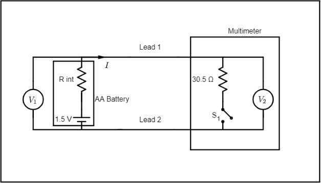
Contemplate the above circuit which represents an AA cell being measured for open circuit voltage (##S_1## open) and underneath load (##S_1## closed). ##S_1 ## open corresponds to the multimeter in unusual DC voltage measurement setting while ##S_1## closed corresponds to the meter being within the “Battery Check” setting. The present flowing within the circuit with ##S_1## closed is definitely calculated by dividing load volts by the mounted resistance worth of 30.5 ohms. The distinction between open circuit voltage and cargo voltage ##Delta V## ought to correspond to the voltage drop throughout the battery’s inner resistance and dividing that by the present yields inner resistance. On this case, the 2 voltmeters proven are redundant since they’re each (in impact) measuring immediately throughout the battery terminals.
The issue with the above circuit diagram is that it exhibits the battery connecting to the voltmeter through a pair of leads of zero resistance. Within the subsequent diagram, the circuit is redrawn to indicate (extra realistically) the battery linked to the voltmeter through a pair of leads of mounted resistance.
The voltage distinction between cell emf and cargo voltage ##V_2## ie: ##Delta V_2## now represents the voltage drop throughout battery inner resistance in collection with lead resistance. So in essence the battery’s inner resistance has been ‘prolonged’ to incorporate lead resistance. In impact, we might return to our first circuit and substitute the battery’s inner resistance with its authentic worth plus the mixed lead resistance.
If we had been incautious sufficient to utilize a battery holder (relatively than putting meter probes immediately onto the battery terminals), we might introduce an extra ‘extension’ of inner resistance on account of the battery holder’s “fitment resistance”. Because of this, the probes of Voltmeter ##V_1## should certainly be in direct contact with the battery terminals in order that they don’t measure something aside from the voltage drop throughout the battery’s inner resistance.
The above association is equal to a normal 4-wire measurement of inner resistance since Voltmeter ##V_2## could possibly be changed by an ammeter in order that present is immediately measured. It isn’t a priority that the ammeter would add resistance to the circuit so long as we guarantee voltmeter ##V_1## measures immediately throughout the battery terminals. Then ##r_i=frac{Delta V_1}{I}## as earlier than. An in depth description of the 4-wire measurement of inner resistance is supplied by PF consumer @DaveE in one of many posts from a thread on this identical subject (battery inner resistance). The reader could be well-advised to review this description taking cautious observe of the experimental element. We regard this because the “gold customary” for measuring the inner resistance of AA cells.
The benefit of the association within the circuit diagram(s) above is that it permits further low resistance measurements different than simply battery inner resistance. For instance within the second circuit diagram above, we will simply get hold of the meter’s lead resistance because the voltage drop throughout the (mixed) leads is just ##V_1-V_2##. Present (as earlier than) is obtained as ##frac{V_2}{30.5}## and a easy Ohm’s regulation calculation then offers the (mixed) lead resistance. As soon as we have now established a worth for lead resistance, there’s nothing to stop us from inserting further resistance between ##V_1## and ##V_2## and measuring the modified voltage drop. The worth of complete circuit resistance could also be simply calculated by Ohm’s regulation and the deduction of lead resistance plus battery inner resistance supplies a measure of the extra inserted resistance.
A last level price noting is that an ‘upmarket’ industrial meter such because the Fluke 87 can measure low resistance to the identical or higher order of accuracy. A selected instruction given in an “Purposes Notice” on low resistance measurement, is to attach leads collectively and internally document lead resistance in order that its worth might subsequently be “zeroed out”. The rationale for doing that is precisely as described above.
Appendix B: Measuring “Battery Check” Resistance
That is most likely the only ever utility of Ohm’s Regulation! When set to “battery take a look at”, the multimeter reads a voltage throughout a hard and fast resistive load. All that must be finished is to position an ammeter and variable resistor (an uncovered pencil lead was used) in collection with the multimeter’s inner “battery take a look at” resistor. When this circuit is powered from an AA battery, present varies with (exterior) resistance so a set of present/voltage readings could also be taken and plotted on a regression curve. Since ##V=IR##, the gradient of the plot offers the worth of the “battery take a look at” resistance worth.
https://www.desmos.com/calculator/7zojmulw95
References
[ad_2]