Programming an ATmega8A utilizing Arduino
[ad_1]
If you’re excited by programming and electronics, you in all probability don’t want an introduction to Arduino. If you wish to make your Arduino initiatives everlasting, then it’s a good suggestion to make use of solo microcontrollers quite than Arduino boards within the last setup. Whereas Arduino boards are nice for prototyping, shopping for an Arduino board for every challenge might not be very budget-friendly. Single microcontrollers typically price lower than a full Arduino board. In some instances, one may have multiple microcontroller for his or her challenge, and in that scenario, utilizing two Arduino boards might not be the most effective resolution. The flexibility to program microcontrollers with Arduino will permit customers to write down supply code in C after which merely add it to the MCU.
On this article, I’ll present you tips on how to program an ATmega8A microcontroller utilizing Arduino. I’ll assume that you’ve some fundamental expertise in Arduino. With out additional ado, let’s get began.
{Hardware} Necessities
- An Arduino board (boards with ATmel AVR microcontrollers, like Uno, Mega, and many others.; ##3.3~mathrm{V}## boards like Due or Zero are usually not most well-liked) with a USB cable,
- ATmega8A microcontroller,
- A breadboard,
- Two ##22~mathrm{pF}## capacitors,
- One ##100~mathrm{nF}## capacitor,
- One ##2.2~mathrm{mu F}## capacitor,
- One ##16~mathrm{MHz}## or ##11.0592~mathrm{MHz}## crystal,
- One ##10~mathrm{kOmega}## resistor,
- One ##330~Omega## resistor,
- One/two LEDs,
- Jumper wires.
Terminology and model
I ought to briefly point out the terminology we might be utilizing. You’ve gotten an Arduino board (Uno, Mega, and many others.) which itself has a microcontroller (“MCU” briefly). For instance, the Uno board has an ATmega328P, whereas the Mega 2560 board has the ATmega2560. This MCU might be known as the “on-board microcontroller” to differentiate it from the ATmega8A.
We might be referring to 4 kinds of pins on this article:
- The pins on the Arduino board. You utilize these pin numbers instantly within the Arduino sketch, like digital pin 13 or analog pin A2.
- The pins of the onboard microcontroller. These are related to the assorted pins on the Arduino board, however the mapping differs from one Arduino board to a different. So, when vital, we could instantly consult with/entry some pins of the onboard MCU quite than the corresponding pins on the Arduino board.
- The native pins/ports of the ATmega8A. These are named PCx, PDx, PBx, and so forth. For particulars, consult with the pinout diagram within the ATmega8A datasheet.
- The Arduino pins of the ATmega8A. These are the pin numbers you can be utilizing in your sketch that might be uploaded to the ATmega8A. There’s a good pinout diagram that exhibits which native pin of the ATmega8A corresponds to which Arduino pin quantity; we’ll come to it later.
Lastly, all sketches and steps on this article have been written w.r.t. Arduino IDE v1.8.13. These steps could change with main revisions within the IDE, and I’ll attempt to hold the article updated so far as attainable.
Getting ready the Arduino board
- Plug the Arduino into your pc through the USB cable, and ensure the Arduino IDE can detect it (go to Instruments ##rightarrow## Get Board information; if nothing is proven, the IDE tells you to pick a port, and the Ports menu is greyed out, your Arduino has not been detected by your pc).
- Open the
ArduinoISPsketch: Go to File ##rightarrow## Examples ##rightarrow## ArduinoISP ##rightarrow## ArduinoISP. - Make sure that the board definition within the IDE is ready as per your Arduino board (Instruments ##rightarrow## Board) and the programmer is ready to
AVRISP mkII(Instruments ##rightarrow## Programmer). - Add the
ArduinoISPsketch to your Arduino.
Putting in the board definition for ATmega8A
We will use the MiniCore board definition by MCUdude. On this article, we’re utilizing v2.1.3, which is the newest on the time of writing. To put in the board, please observe the steps within the GitHub web page.
Organising the circuit
At this juncture, it’s best to first examine the pinout diagram close to the underside of the README.md of the MiniCore GitHub repo. The pinout diagram exhibits which native pin of the ATmega8A corresponds to which Arduino pin. When writing your supply code for the ATmega8A, you’ll use these Arduino pin numbers to consult with the pins. The pinout diagram can even aid you in wiring the {hardware} later.
To be able to program the ATmega8A, we will be connecting the MOSI (Grasp Out – Slave In), MISO (Grasp In – Slave Out), and SCK (Serial Clock) pins on the ATmega8A to the corresponding pins of the onboard MCU. These pins will permit the onboard MCU to speak with the ATmega8A.
As we have now said earlier, the mapping from the pins of the onboard MCU to the pins on the Arduino board differs from one board to a different. Therefore, we will be utilizing the ICSP header pins on the Arduino board, the pinout of which might be common and invariant throughout Arduino boards. Word that boards like Uno and Mega (which have a separate chip for USB communication) have two units of ICSP headers. We’ll use the headers for the principle microcontroller, and these typically have the label “ICSP” beside them.
The headers have the next pinout:
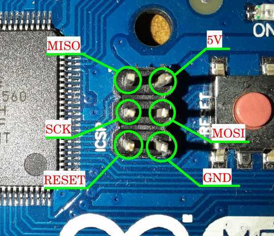
The pinout of the ICSP headers can be proven within the ArduinoISP sketch within the feedback.
The complete circuit, connecting the Arduino to the ATmega8A, is proven within the following diagram:
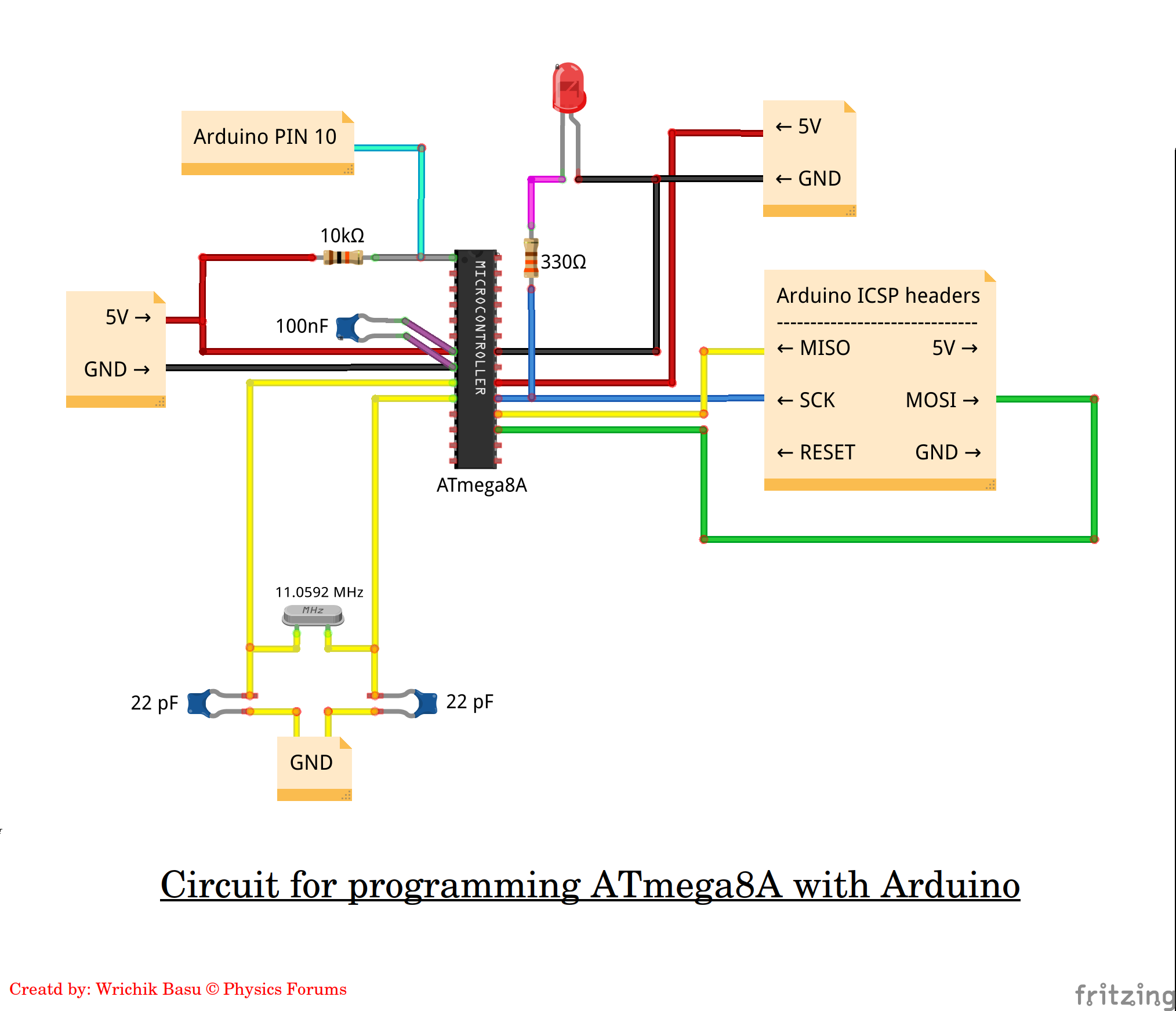
A couple of factors to notice:
- We do not use the ##mathtt{RESET}## pin of the ICSP header. We’ve related the ##overline{mathtt{RESET}}## (pin PC6) of the ATmega8A to pin 10 of the Arduino board and not to the ICSP header. The ##mathtt{RESET}## pin of the ICSP header corresponds to the ##overline{mathtt{RESET}}## of the on-board MCU. Resetting the ATmega8A and the onboard MCU are two totally different tales and are usually not associated to one another. We should always be capable to reset the ATmega8A independently after we are programming it. To this impact, the
ArduinoISPsketch, by default, makes use of the digital pin 10 on the Arduino board. Therefore, regardless of the board you’re utilizing, the ##overline{mathtt{RESET}}## of the ATmega8A will all the time be related to digital pin 10 on the Arduino board. You might change this pin as per your want by modifying theArduinoISPsketch. - I’ve used an ##11.0592~mathrm{MHz}## crystal. You’ll be able to select any crystal from this checklist.
- Whereas burning the bootloader or importing a sketch, it’s a must to compulsorily energy the ATmega8A from the Arduino board. You might use the
5VandGNDpins on the ICSP header, or instantly hook up with the5VandGNDsockets on the Arduino board. If you’re prototyping on a breadboard, then you could join the ability rails to the Arduino board.
Burning the bootloader
After getting arrange the circuit, as proven above, you’re able to burn the bootloader.
- First, it’s a must to select the right board definition. Within the Arduino IDE, go to Instruments ##rightarrow## Boards ##rightarrow## MiniCore ##rightarrow## ATmega8.
- Set the programmer to
Arduino as ISP (MiniCore)[Tools ##rightarrow## Programmer ##rightarrow## Arduino as ISP (MiniCore)]. - Select the clock (crystal) you might have used (Instruments ##rightarrow## Clock ##rightarrow## …).
- The opposite choices could also be as follows:
- BOD: ##2.7~mathrm{V}, ##
- EEPROM: EEPROM retained,
- Compiler LTO: LTO enabled
- Bootloader: Sure (UART0).
- Go to File ##rightarrow## Preferences ##rightarrow## Settings tab ##rightarrow## “Present verbose output throughout…” and choose each “Compilation” and “Add” checkboxes. This can aid you troubleshoot any errors that will come up.
- Click on on Instruments ##rightarrow## Burn bootloader.
If every part goes properly, there needs to be a message within the IDE: “Completed burning bootloader“; if there are errors, scroll by means of the article to the “Coping with runtime errors” part. When you’ve got related the LED to the SCK line of the ATmega8A as proven within the circuit diagram, it ought to begin blinking after this if the burn succeeds.
Importing sketches to the ATmega8A
To add any sketch,
- Be sure you have chosen the right board definition. The underside-right nook of the IDE ought to present you the chosen board choices.
- Compile the sketch.
- On the Arduino board, join a ##2.2~mathrm{mu F}## capacitor between the
RESETandGNDpins. This can ensure that the on-board MCU stays reset through the add course of. (If you’re utilizing the Uno board, you could detach the on-board microcontroller by eradicating it from its IC base.) - The circuit would be the identical because it was if you had burnt the bootloader.
- Go to Sketch ##rightarrow## Add utilizing Programmer.
Check with a Blink sketch
Now you’re able to add sketches to the ATmega8A. We will check with the next Blink sketch, which is akin to the “HelloWorld” program.
void setup() {
    pinMode(17, OUTPUT);
}

void loop() {
    digitalWrite(17, HIGH);
    delay(1000);
    digitalWrite(17, LOW);
    delay(1000);
}
Word that digital pin no. 17 of the ATmega8A corresponds to port PC3. It is best to be capable to find this pin on the pinout diagram given within the MiniCore repo.
Join a LED with a resistor between digital pin 17 of the ATmega8A and GND, and add the sketch. If every part goes effective, the LED ought to begin blinking. When you disconnect and reconnect energy to the ATmega8A, the LED ought to begin blinking once more. Congratulations! You’ve gotten efficiently uploaded your first sketch to the ATmega8A.
Suitable microcontrollers
Though we have now used the ATmega8A on this article to display the process, you may program many different microcontrollers in a similar way. MCUdude has written many different board definitions like MicroCore, MajorCore, MightyCore, and so forth. The checklist of supported microcontrollers is given within the GitHub repos. As an example, MiniCore helps not solely the ATmega8A, but additionally ATmega48, ATmega88, ATmega168, ATmega328, and ATmega328PB, and these will be programmed equally. For different microcontrollers, ensure you examine the pinout and minimal setup diagrams and modify the circuit accordingly.
Some factors to remember
- As soon as a sketch is uploaded, you could disconnect all pins from the Arduino board. You might present the ability supply to the microcontroller externally with out utilizing an Arduino (like a 9V battery with a LM7805 voltage regulator, or instantly from the mains AC utilizing an AC-DC adapter).
- Not all Arduino libraries have been carried out in different microcontrollers. While you compile your sketch, you’re going to get errors if the library you’re utilizing is just not carried out.
- Microcontrollers have various sizes of flash reminiscence. In case your sketch requires extra reminiscence than is obtainable, the compiler will throw an error. Word that the bootloader makes use of 513 bytes of flash reminiscence.
- You might use an inner clock and thereby achieve two further pins. However until vital, it’s preferable to make use of an exterior clock.
- By default, LTO is disabled within the MiniCore board definition. This has been finished to keep up backward compatibility with earlier variations of the IDE. It is suggested to allow LTO, which might shrink your code and scale back its measurement on the time of linking. In some board definitions by MCUdude, LTO is enabled by default. Word that if you wish to change the LTO choice, it isn’t essential to burn the bootloader once more. You might merely change the choice and compile your code once more.
- It isn’t essential to burn the bootloader each time you want to add a sketch. It’s, nonetheless, essential to burn the bootloader once more in case you need to change any of the next choices:
- BOD
- Clock frequency
- EEPROM choice
Coping with runtime errors
There are two kinds of errors that you could be regularly encounter whereas importing a sketch or burning the bootloader:
- Gadget signature invalid, and
- Timeout after no response from the microcontroller.
The most typical motive for these errors is connections. Examine when you’ve got a unfastened connection someplace, and confirm that you’ve arrange the circuit correctly. Examine connections for continuity with a multimeter. Generally, the IC could not have been firmly connected to the breadboard, so examine that too. Whereas importing a sketch, ensure you join the capacitor between RESET and GND within the Arduino board.
That’s all for this text. Thanks for studying by means of it, and I hope you will discover it useful.
I wish to take this chance to thank Greg Bernhardt, the creator, and admin of Physics Boards, for always motivating us to write down articles within the Insights Weblog and offering us with a platform the place we will share our data. I additionally thank the Mentors of Physics Boards for his or her dedication and laborious work (which is totally voluntary), with out which the web site couldn’t have turn into what it’s right this moment.
Questions, feedback, and solutions are all the time welcome.
[ad_2]